NACA0012 Hinge
Control-Surface Hinge Design & Structural Validation
A compact aerospace mechanical-design study linking a public NACA0012 reference section to a 75%-chord hinge axis, analytical load and stress calculations, SolidWorks mechanism design, local contact FEA and an explicit analytical-to-FEA comparison.
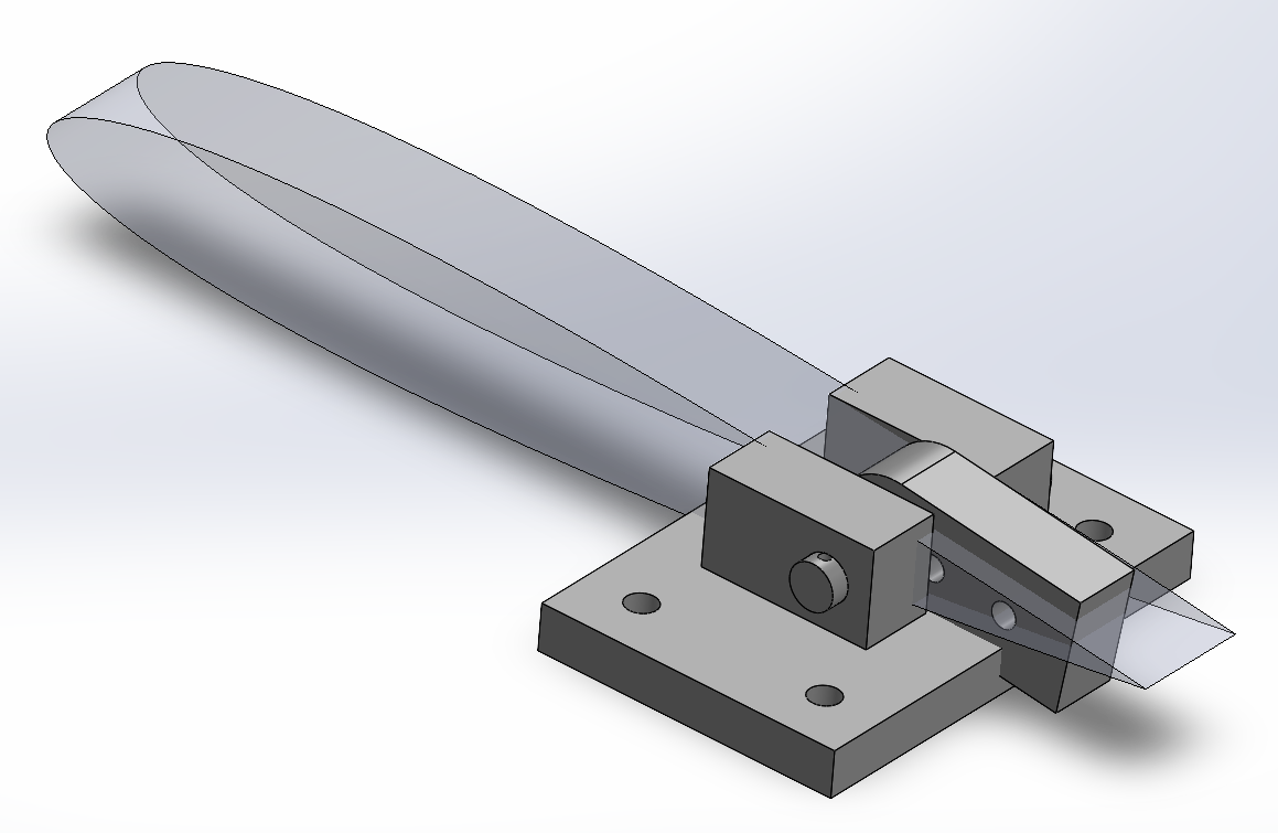
From aerodynamic reference to load path.
The project was built as one traceable chain rather than as disconnected CAD and simulation exercises. The NACA0012 profile defines the geometric context, the control-surface load model generates the hinge demand, analytical sizing establishes the first structural baseline, and SolidWorks Simulation resolves the local effects around the pin/lug/bracket interfaces.
A public geometry with an original hinge study.
The aerodynamic context uses a non-proprietary NACA0012 section with a 300 mm chord. The control-surface break is placed at 75% chord, leaving a 75 mm control-surface chord. The hinge mechanism is an original portfolio load-path demonstrator rather than a reconstruction of proprietary aircraft hardware.
| Parameter | Value |
|---|---|
| Main chord | 300 mm |
| Hinge station | 225 mm |
| Control-surface chord | 75 mm |
| Control-surface span | 600 mm |
| Control-surface area | 0.0450 m² |
| Horn arm | 40 mm |
| Pin diameter | 11.8 mm |
| Lug hole diameter | 12.2 mm |
| Lug thickness | 18 mm |
| Bracket ear thickness | 25 mm each |
| Aluminum components | 7075-T6 |
| Hinge pin | 17-4 PH stainless steel |
Geometry and mechanism tied to the same hinge axis.
The context assembly is used to show how the abstract 75%-chord aerodynamic hinge station maps into the mechanical subassembly.
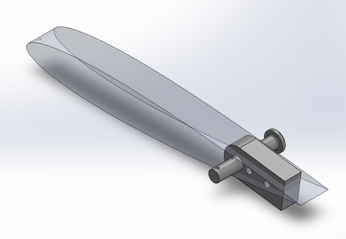
Transparent context view linking the NACA0012 profile to the structural hinge assembly.
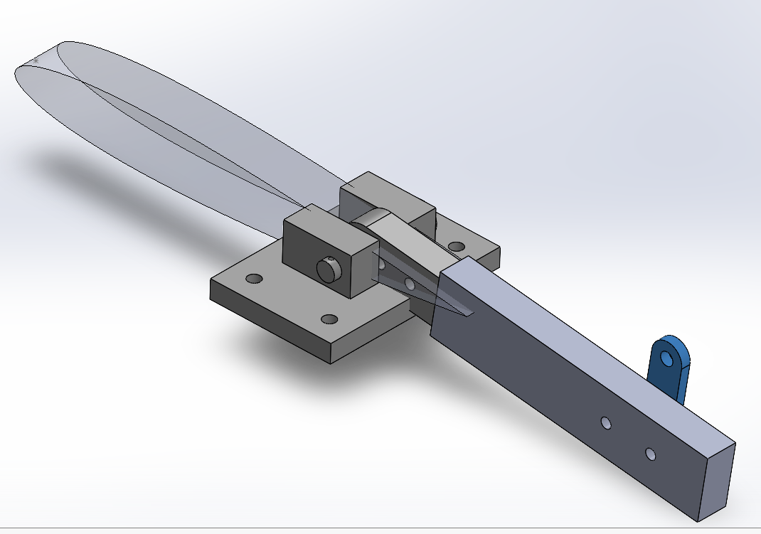
Local hinge hardware used for the structural load-path study.
Nominal sizing first. Local stress second.
The maximum screened condition was 50 m/s and 25° control deflection. With the project load model and a 1.5 structural load factor, the design hinge reaction is 322.33 N.
| Quantity | Result |
|---|---|
| Dynamic pressure | 1531.25 Pa |
| Normal-force coefficient | 1.7820 |
| Control-surface force | 122.79 N |
| Hinge moment | 3.684 N·m |
| Horn force | 92.09 N |
| Design hinge reaction | 322.33 N |
| MATLAB nominal pin von Mises stress | 21.632 MPa |
| SolidWorks FEA local peak von Mises stress | 35.730 MPa |
| FEA / analytical stress ratio | 1.65× |
| Maximum displacement | 0.3716 mm |
| Maximum equivalent strain | 3.084 × 10⁻⁴ |
| Minimum reported FEA FoS | 14.08 |
Stress, strain and displacement at the hinge.
The plots below are shown at a deformation scale of 1 where applicable.
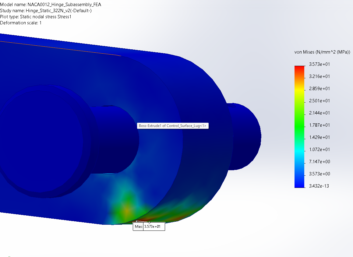
Local von Mises peak: 35.73 MPa near the load-transfer region.
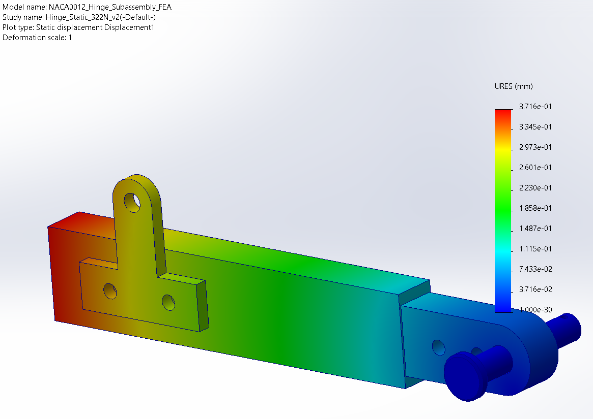
Maximum resultant displacement: 0.3716 mm.
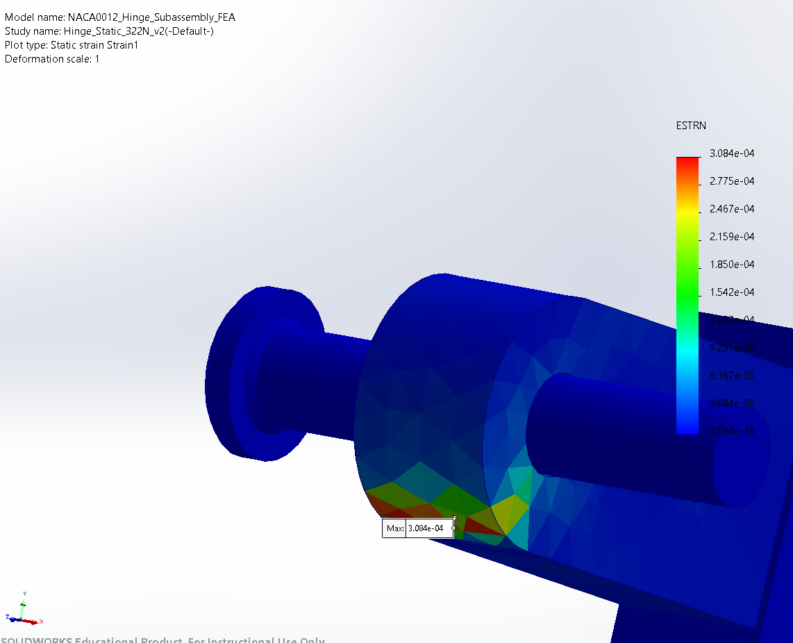
Maximum equivalent strain: 3.084 × 10⁻⁴.
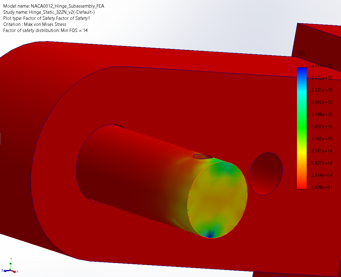
Minimum reported FEA factor of safety: 14.08. Extremely large values in nearly unstressed regions are not used as design metrics.
FEA is not being used to decorate the CAD.
The analytical model answers the first sizing question quickly and transparently. The FEA model then asks a different question: where does the real geometry concentrate the load once pin/lug/bracket contact is represented?
The result is a 1.65× increase from nominal analytical pin stress to local FEA peak stress. That difference is kept in the project rather than tuned away because it illustrates the practical role of local simulation after hand/analytical sizing.
The final investigated static configuration remains above the project screening target FoS of 3.0 within the stated model assumptions.
What this project does not prove.
This is a portfolio-level engineering study, not flight-hardware substantiation or certification evidence. It does not include fatigue or spectrum loading, full airframe/control-surface flexibility, detailed fastener preload, tolerance sensitivity, nonlinear material behaviour, certification load cases or a documented mesh-convergence study.
The hinge assembly demonstrates the mechanical load path and analysis workflow. It is not claimed to be a packaging-optimized internal hinge installation inside a real NACA0012 wing.
A lightweight 2-D SU2 aerodynamic check was used during the broader workflow, but the exact original SU2 configuration, mesh and coefficient-history files were not available in the final publishing workspace. No solver output has been fabricated to fill that gap.
Reference basis: the NACA0012 geometry is based on the public NACA four-digit airfoil definition and NACA Report 460. SU2 is referenced only as an open-source aerodynamic workflow used during the project.